
5'' Retro Motorcycle Headlight for CG125 GN125 For Harley Suzuki Honda cb400 BWM Beam Bulb Cafe Racer Motorbike |
US $7.99


Новое поступление
Характеристики
*Текущая стоимость 7 927,15 уже могла изменится. Что бы узнать актуальную цену и проверить наличие товара, нажмите "Добавить в корзину"
| Месяц | Минимальная цена | Макс. стоимость | Цена |
|---|---|---|---|
| Feb-18-2026 | 10067.41 руб. | 10268.47 руб. | 10167.5 руб. |
| Jan-18-2026 | 8165.30 руб. | 8328.59 руб. | 8246.5 руб. |
| Dec-18-2025 | 9909.17 руб. | 10107.10 руб. | 10008 руб. |
| Nov-18-2025 | 9829.93 руб. | 10026.14 руб. | 9927.5 руб. |
| Oct-18-2025 | 7848.74 руб. | 8005.17 руб. | 7926.5 руб. |
| Sep-18-2025 | 9671.47 руб. | 9864.26 руб. | 9767.5 руб. |
| Aug-18-2025 | 9592.59 руб. | 9784.46 руб. | 9688 руб. |
| Jul-18-2025 | 9512.80 руб. | 9702.89 руб. | 9607 руб. |
Описание товара


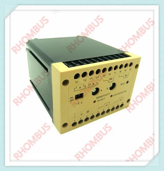
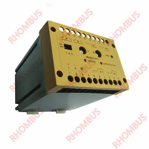
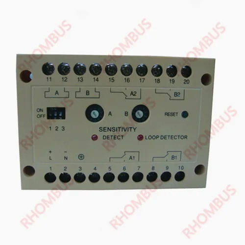
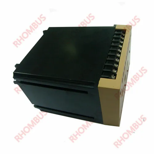
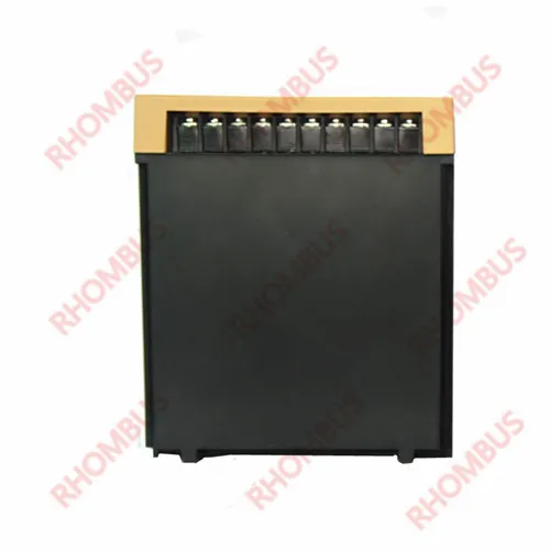
2-Channel Traffic Inductive Loop Vehicle Detector Daul Control
Application
To download the manual please click here
Technical Data
Principle
It is based on a change in the inductance within the loop which is caused by the metallic components of passing
vehicles. The changes are picked up and evaluated by a microprocessor.

Tune
The tuning process is automatically. It can tune with the connected loop automatically when detector started or reset.
The tuning range is from 50µH to 1000µH, and such wide tuning range ensures low requirements for the loop and wiring.
Once tuned, any inductance changes will feedback to the compensation circuit in detector to ensure normal work.
Adjustable sensitivity
The sensitivity relays on some factors, such as loop size, loop turns, wiring length, whether or not there are metals under the loop
and so on. When in low sensitivity, the detector will detect vehicles with high chassis or trailers correctly, but can’t detect cars,
bicycles and other small metals. The sensitivity adjust button is the rotary encoder switch on the panel, “0” with low sensitivity
and “9” with high sensitivity. A switch on left is corresponding to loop A, while B on right is corresponding to loop B. While using,
adjust the sensitivity from low to high, to find a proper one for steady state.
Reaction time
Its definition is that the time starting from the metal enters into the loop and ending when the detector gives indication signals.
It is specialized and optimized for parking lots.
Frequency adjustment

There are four frequencies to choose for users. Open the panel, pull out the circuit board, and dial SW1 (channel A) or SW2
(channel B) with small screwdriver. You can change the frequencies to avoid interferes from the environments or the two adjacent
inductive loops.
Output mode of relay
Every channel has two relay outputs in our detectors. There are two relays A1 and A2 with channel A. And there are two relays B1
and B2 with channel B. Relay A1 and B1 are existing output (on when metals on the loop and off when metals leaving). Relay A2
and B2 are multifunctional output set by the three bit code switch on the left of the panel. Operate as follows:

Working state
After connecting with the power supply the detector can calibrate itself automatically and the two red lights are on at the same
time,which will continue for 2s. During the calibration, the red light always lasts two seconds. (Note: there should be no cars
parked in loop). After the success of calibration, the two panel indicator goes out. In normal working condition, when the car
passed the loop,the panel on the corresponding indicator light and a corresponding relay action (refer to "relay output");
if the calibration process was not detected the loop, the corresponding indicator lights will be kept flashing.
Loop installation sketch map

Смотрите так же другие товары:


